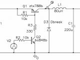
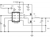
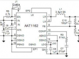
Dc to Dc Converter Circuit Diagram Step Down as well as schematic diagrams are drawn here only for the understanding working of this circuit. DC to DC converter basically referred to the electronic circuits and it’s an electronic device or circuitry that’s convert direct current or voltages one level to another level of direct current and its may used as power converters. There are two types of convertors one is known as step up dc to dc convertor and second one is known as step down dc to dc convertor. But we discussed only one of them and talk about the step down dc to dc convertor. Dc to dc voltage step down converter is also known as buck convertor and the simplest work of this convertor to reduce the dc voltages one level to another level. The reduction of dc voltages depends upon the requirement of the usage and this circuitry is regulating the voltage after the reduction of voltage. Normally this circuit is used to reduce the voltage up to 12- 24 dc voltages. But you can design this circuitry according to their requirements.
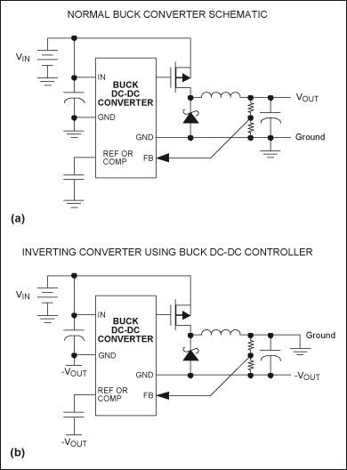
The basic operation of this circuitry which used the buck inductor to control the current in this circuit controlled with the different kinds of diodes, transistors or mostly used diodes because it’s assumed that the voltage drops is zero with the switches to ensure that the voltage drop during the open condition in the inductors should be zero. Normally dc to dc step down convertor to control the motors speed, to increase the efficiency of electronic devices, use in laptop, computers, mobile phones, and output voltage regulators and other so many devices. Now this time evolution in the fields of electronics this circuitry is commonly available in shape of small chip of ICs but main operation and design of converter is the same which used to step down the dc voltages.
